This is the circuit diagram for the ignition system for the Yamaha Ténéré 700 motorcycle, hope its helpful. This diagram comes from the official Yamaha Ténéré 700 workshop manual, if you are want access to hundreds of pages of detailed know how, consider clicking this link ( Yamaha Ténéré 7000 Workshop Manual ) or download direct from the button below.

1. Main switch
8. Ignition fuse
17.Battery
18.Engine ground
19.Main fuse
23.Relay unit (diode)
26.Joint coupler
27.Sidestand switch
29.Crankshaft position sensor
32.ECU (Engine Control Unit)
33.Ignition coil #1
34.Ignition coil #2
35.Spark plug
43.Lean angle sensor
66.Gear position switch
67.Handlebar switch (right)
69.Engine stop switch
C. for XTZ690
D. for XTZ690-U
ENGINE STOPPING DUE TO SIDESTAND OPERATION
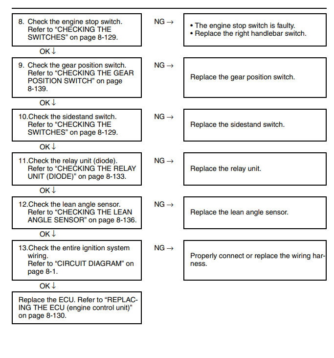
When the engine is running and the transmission is in gear, the engine will stop if the sidestand is moved down. This is because the electric current from the ECU does not flow to the ignition coils or fuel injectors when the gear position switch (neutral circuit) or sidestand switch is open.
However, the engine continues to run under the following conditions:
• The transmission is in gear (the neutral circuit of the gear position switch is open) and the sidestand is up (the sidestand switch circuit is closed).
• The transmission is in neutral (the neutral circuit of the gear position switch is closed) and the sidestand is down (the sidestand switch circuit is open).

1. Battery
2. Main fuse
3. Main switch
4. Ignition fuse
5. Engine stop switch
6. Ignition coil
7. Spark plug
8. ECU (Engine Control Unit)
9. Relay unit (diode)
10.Sidestand switch
11.Gear position switch
Troubleshooting


